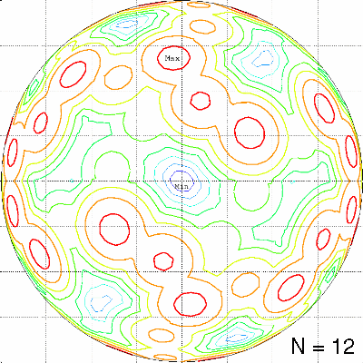
What's new? Results sorted by date. (Last update: July 23, 2011).
If we ignore all those features that make "state of the art" ray-traced pictures look "realistic" e.g. specular reflection, ambient lighting, colour dependance etc. then the luminance of an illuminated surface is only determined by the geometric relation of the surface normal vector and the direction of the incoming light.
A very concise description of the terminology to be used when describing the measurement of light is "Radiometry and photometry FAQ" by James M.Palmer.
For a discussion of the terminology see also "Brightness, Luminance and Confusion" by Charles P. HalstedPlease forgive me, if my terminology is inaccurate, or even wrong. Although I studied physics in the early 1970s, light is not my speciality and my native language is not English ;-)
Or even better: help me improving it by sending me a suggestion by E-mail.
For n light sources we have
If the light sources are very far away from the target, then the influence of the source is only determined by its direction vector or more precisely the difference vector between source and target ("directional light") and its intensity.
The most simple object to illuminate is a sphere. It is assumed that illumination of the the target sphere is only by perfectly diffuse reflection. If Lambert's law holds, the viewing angle has no influence on the luminance seen by an observer. Ambient reflection and specular reflection are assumed to be absent.
Here are some examples, created with POVRAY, version 3.0. The current version can be found at POVRAY's web site.
A single light source illuminates one side of the sphere, producing a maximum luminance of 1.0 exactly at its angular location. If the target sphere is located at the origin and has a radius of 1.0, and the direction of the light source is exactly above the north pole (0,0,1), then I = max (0,z).
The following description is from James M. Palmer's "Radiometry and photometry FAQ":
A lambertian sphere illuminated by a distant point source will display a radiance
which is maximum at the surface where the local normal coincides with the
incoming beam. The radiance will fall off with a cosine dependence to zero at the
terminator. If the intensity (integrated radiance over area) is unity when viewing
from the source, then the intensity when viewing from the side is 1/p.
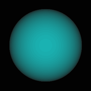
Lines of equal luminance are circles of equal latitude (theta=constant in a spherical phi,theta co-ordinate system), as can be seen in the following picture:

If more than one light source is present, a combined luminance pattern is created. In the following pictures

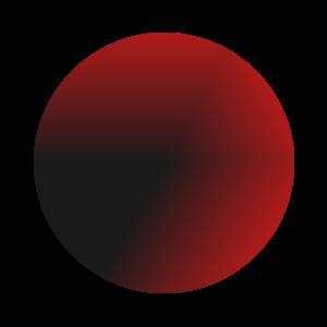
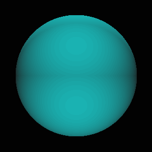
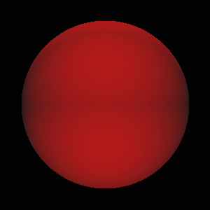
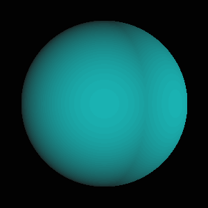
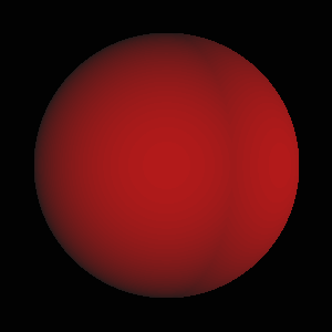
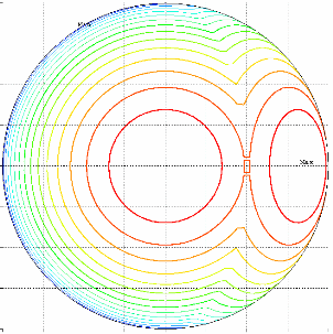
With two and also with three sources, there remains always a region (at least two points for n=3) with I=0.
The "best" configuration for n=2 is putting the sources at opposite sides of the sphere (e.g. above the north and south poles), leaving a dark ring around the equator.
Three sources pose the first, trivial optimization problem: How to arrange the 3 sources to minimize the maximum of luminance over the whole sphere? The only solution is an arrangement on an equilateral triangle, whose plane contains the origin, with arbitrary orientation (e.g. the equator plane). This is the only configuration that avoids mutual angles less than 120 Degrees, which would create a combined intensity maximum >1.0 between two sources.
Starting with four sources, arrangements with I>0 over the whole sphere
can be constructed. The most obvious arrangement for 4 sources is the
regular tetrahedron. The following figures
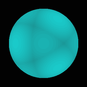
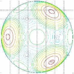
When looking at this figure, the question arises, if the light sources can be put in some "optimal" arrangement that produces a "uniform" luminance distribution over the whole surface of the sphere.
To describe the "quality" of an arrangement, there are several choices for a target function, 3 different target functions are considered:A point light source far away from a sphere (e.g. a star shining on the earth produces an luminance distribution on the earth's surface that is a function of the relative angle between the surface normal and the direction of the incoming light. The luminance is given by the simple cosinus law. If the light source is arranged exactly above the north pole, the lines of equal luminance are lines of equal latitude. At the equator the luminance has dropped to zero. As the star is invisible, the southern hemisphere will have zero luminance (darkness) from the star above the north pole. If more than one star (light source) is present, the luminance at any point will be the sum of the scalar products of the local surface normal vector with the directions of the incoming contributions from all sources. Only visible sources will contribute, those on the other hemisphere contribute nothing to the local luminance.
This class of problems has some relation to inertia confined fusion (ICF) devices, where multiple light beams of high energy lasers are focussed on a small deuterium/tritium target with the aim of compressing the target material to the conditions necessary for fusion reactions. A former version of LLNL's web page about inertial fusion energy had schematic diagrams showing "How inertial fusion works" and on so-called "direct drive" targets that are "uniformly illuminated" from all directions. See the following figure:

The physical processes during the energy transfer from the light beams to the target material are rather complicated due to the refractive and absorbtion properties of the plasma surrounding the target.
The direct drive approach is now considered as almost infeasible and has been abandoned in favor of the so-called
indirect-drive approach.
For a more detailed description see: S.Skupsky, K.Lee: Uniformity of energy deposition for laser driven fusion. J.Appl.Phys. 54 (7), pp.3662-3671, July 1983.
It has been pointed out to me in a private correspondence, that the geometrical part of this problem even has a perfect solution, if one manages to give the laser beams an intensity profile that gives rise to an energy deposition ~cos2(theta) on the target, where theta is the angle relative to the direction of the incoming beam. It is then possible to find arrangements, which produce a constant illumination on the whole target sphere. The conditions for optimal arrangements were first described in the following reference:
A.J. Schmitt: Absolutely Uniform Illumination of Laser Fusion
Pellets, NRL Memorandum Report 5221, Naval Research Laboratory Washington D.C., February 17, 1984, also published in Appl. Phys. Lett. 44, pp. 399-401 (1984). The NRL report is available for download.
A similar derivation and some examples consisting of rings of beams with uniform spacing in azimuth and pair-wise opposed beams in rings on the upper and lower hemisphere are given in:
W.W. Simmons: Simple analytic solutions for uniform irradiation of spherical targets. In: First Annual International Conference on Solid State Lasers for Application to Inertial Confinement Fusion, Michel Andre and Howard T. Powell, Editors, Proc. SPIE 2633, pp. 249-254 (1995)
Optimal arrangements with a perfect solution are only possible for N even and >=6.
I have tried to find some good (minimize difference) numerical solutions for odd N, assuming cosine shaped beam profiles and no angular dependence of absorption on the target sphere.
The character of the solutions differs from that for constant intensity beams, as can be seen in the following example for N=17:
The Laboratory for Laser Energetics at Rochester, NY operates the 60 beam OMEGA facility specifically tailored for direct drive ICF experiments. A detailed description of OMEGA is found in the National Laser Users' Facility User's Guide, including pictures of the beam configuration and of the radial intensity profiles of the beams (Fig. 2.11), which is indeed not far from the cosine profile mentioned above.
Some years ago I became interested in optimization problems with simple definition, which were suitable to test numerical methods for global optimization. When looking for examples of difficult optimization problems, especially those with multiple extrema, my attention was caught by the famous placement problems of points on a sphere. Those problems have a very simple definition, but are rather difficult to solve.
For the history of those problems and solutions for low numbers of points the bookL.Fejes Tóth: Lagerungen in der Ebene auf der Kugel und im Raum, Zweite Auflage, Springer-Verlag, Berlin, Heidelberg 1972 (in German)
is still fascinating to read. Also worthwile reading (in German ;-) is the classical articleK. Schütte and B.L. van der Waerden: Auf welcher Kugel haben 5, 6, 7, 8 oder 9 Punkte mit Mindestabstand Eins Platz? Math. Annalen, Bd. 123, pp. 96-124 (1951)
There are at least four well known problems with different criteria, which are described at the Home Page of Neil J.A. Sloane.
Dave A. Kottwitz: The Densest Packing of Equal Circles on a Sphere. Acta Cryst. (1991). A47, pp. 158-165
Most edges of the convex hull of the optimal configurations have the same (minimal) length. I have compiled a table of edge lengths and raytraced pictures showing the distribution of minimal edges for N<=50. Many of the configurations are symmetric; a table with a description of the symmetries (cycles and symmetry group) for N<=50 is available here (Caution: German text :-). An example with coordinates (Phi, Theta, X, Y, Z), list of edges and connectivity is given for N=14. See also: Visualization of this configurationTo my knowledge, the best known solutions of those problems are compiled on the Web Site of Neil Sloane. There are also extensions to higher dimensions than 3. For more information on this topic see the FREQUENTLY-ASKED QUESTIONS ABOUT SPHERES in Dave Rusin's Mathematical Atlas. Anton Sherwood maintains a list of links relating to optimal arrangements of points on a sphere.
During my own attempts to use the covering and maximum volume problems as test cases for various numerical optimization methods, I have created some raytraced pictures of the results.
If you think, that you have a good method for global optimization, trying to run this method on any of those problems will give you a realistic impression, how hard it can be to find global optima for multidimensional problems - compare your solutions with those listed in Neil Sloane's tables!
The placement problems of N points yields a problem with 2*N-3 variables, since 1 point can be kept fixed, e.g. at the north pole of the sphere, and one angle can be kept fixed for a second point (e.g. phi=0). For the remaining points the angles (phi, theta) in a spherical coordinate system can then be used as optimization variables.
The following files are available for download:
The problem of finding optimal configurations consists of two coupled global optimization problems. The "inner" problem is to determine the global minimum and/or maximum of I = sum j=1..n (N dot I_j) over all possible orientations of the surface normal vectors of the sphere, which is then used as target function for the source placement problem. As I have found no reliable, elegant technique to find all optima either analytically or by a numerical optimization procedure and I wanted to avoid the rather tricky coupling of two global numerical optimization problems, a brute force approach is used for this problem.
A grid of equally spaced test points (directions) with a prescribed angular separation on the sphere is created and stored. For the global search an angular resolution of 1 Deg is used, creating approximately 41000 test directions, whereas 0.25 Deg resolution is used to produce the final results (approx. 660000 test directions).
Starting at the north pole, circles of equal latitude with the selected spacing are created. On each of this circles equally spaced test points are created. The first circle around the north pole will have 6 test points, whereas the equator circle will produce 360 test points for 1 Deg angular resolution.
Each function evaluation of the numerical optimization requires to evaluate the sum of scalar products of the N light directions with the local surface normal vector (=coordinates of test point on unit sphere), limited to positive contributions (light does not shine through target sphere). This has to be repeated for all test points on the target sphere. The minimum, maximum or difference of both (dependent on the chosen criterion) is then used as the value of the objective function. For an angular separation of alpha [Deg], the number of test points is approximately ((360/alpha)2)/Pi.
Due to the cutoff property (dark rear side) and the contribution of many potential maxima and minima the objective function has a lot of discontinuities in its derivatives, especially around the mimima.
A triangular grid based on a
covering of the sphere with icosahedral symmetry, available from
N.J.A.Sloane
was produced, using ACM algorithm 772 by R.J. Renka.
Reference: Robert J. Renka, "ALGORITHM 772. STRIPACK: Delaunay
Triangulation and Voronoi Diagram on the Surface of a Sphere", ACM
Trans. Math. Software, Vol. 23, No. 3, Sept. 1997, pp. 416-434.
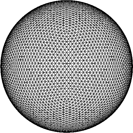
The projections of the source locations and of the luminance pattern on the six surfaces of a cube containing the target sphere are plotted and converted into PDF files that can be displayed using the Adobe Reader. Only the visible part of the triangle grid is displayed. The grid consists of 10140 triangles, created on 5072 points on the target sphere. The configuration used was the icosahedral best covering labeled "13,13" in Neil Sloane's "Spherical Codes with Icosahedral Symmetry".
The first heading line indicates the optimization criterion, the second heading shows the numerical value of the achieved optimum. The third line indicates the view.
The plots show scaled luminance values. The scaling used is
For every number of source points 12 plots are collected in one PDF file. To visualize the source locations, a few artificial contour lines are drawn around the "footprint" of every source. The advantage of this technique is, that also sources at the periphery of the projection become visible.
The accuracy of the result coordinates is of course limited by the selected angular resolution of the test points on the target sphere, which also limits the accuracy of the achieved optimal intensities. A conservative estimate would be to add sin(Alpha) in the pessimistic direction to the best found result.
For N=9 sources the numerical optimization result for the "maximize minimum" problem was I=2.1173186, using test points on the target sphere with Alpha=0.25 Deg angular separation. A pessimistic estimate for the true result would be I_true>I_0.25-sin(0.25Deg)=2.1130. From numerical experiments with different values of Alpha in most cases sin(0.5*Alpha) seems to be a more realistic estimate for the difference between the numerical and the true solution giving I_true>2.1151.
A diagram comparing the deviations of the best results from absolutely uniform luminance and some remarks on the general character of the solutions for the 3 different criteria is available here.
For viewing a configuration and results, click on the numbers in the table.
Best configurations found |
|||
|---|---|---|---|
| N | Maximize Minimum |
Minimize Maximum |
Minimize Difference |
| 1 | 0.0 | 1.0 | 1.0 |
| 2 | 0.0 | 1.0 120 Deg Separation |
1.0 |
| 3 | 0.0 | 1.0 Isosceles Triangle |
1.0 |
| 4 | 0.8164965 Tetrahedron |
1.1547005 Tetrahedron |
0.3382040 Tetrahedron |
| 5 | 0.9396906 Dihedral Order 8 |
1.4142137 Dihedral Order 12 |
0.5178666 Dihedral Order 8 |
| 6 | 1.3340707 Dihedral Order 12 |
1.6506903 Dihedral Order 6 |
0.3438863 Dihedral Order 12 |
| 7 | 1.5926648 Mirror Order 2 |
1.8523984 Cyclic Order 2 |
0.2836353 Mirror Order 2 |
| 8 | 1.8303337 Mirror Order 2 |
2.1128430 Dihedral Order 12 |
0.3361533 |
| 9 | 2.1174936 Cyclic Order 3 |
2.3389220 Cyclic Order 6 |
0.2857277 Cyclic Order 6 |
| 10 | 2.3718607 Cyclic Order 2 |
2.5831981 Mirror Order 2 |
0.2462976 |
| 11 | 2.6259986 | 2.8364630 | 0.2562928 Mirror Order 2 |
| 12 | 2.9073987 Dihedral Order 8 |
3.0849881 | 0.2080100 Dihedral Order 8 |
| 13 | 3.1310258 | 3.3329923 | |
| 14 | 3.3844719 | 3.5890152 | |
| 15 | 3.6322515 | 3.8369949 | |
| 16 | 3.8829281 | 4.0839849 | |
| 17 | 4.1316900 | 4.3336964 | |
| 18 | 4.3824286 | 4.5861354 | |
| 19 | 4.6305666 | 4.8390818 | |
| 20 | 4.8798361 | 5.0889797 |
Question: Where are results for N>20?
Answer: With increasing N, many solutions exist, which are practically equivalent in the achieved value of the chosen objective function. For the "minimize difference" problem one might choose a desired value for the difference near 0.25 and then run the optimization process until a configuration fulfilling this requirement is found. The asymptotic behavior of the optimal solutions for increasing N is an open question, at least for me. Of course, it is also a question of available computer resources, how far to continue the search. If you have too much idle time available on your 1000-processor MPP machine,
send me an E-mail and we can continue searching up to whatever N you want ;-)
Although I did not find a proof for this, the luminance distributions
produced on the target sphere by all optimal source configurations seem
to have the property
I(x,y,z) = I(-x,-y,-z)
i.e. the intensities at antipode locations are equal (for N>1).
This property is also found for the non-symmetric source configurations.
The numerical solutions for the illumination problem (minimize difference between maximum and minimum luminance on target sphere) with beams having a cosine shaped radial intensity profile indicate the following conjecture:
Optimal solutions of this problem fulfill I(x,y,z) + I(-x,-y,-z) = N/3
In other words: The sum of energy densities at antipodal points is constant.
My currently best numerical solution for N=11 does not fulfill this criterion. If I should fail to find a better solution, then the conjecture has to be limited to N>11.
My most recent results indicate, that there exists a systematic way to construct very good (maybe the best possible) solutions for odd N>=15: Arrange the maximum possible odd number of beams with equal angular distance in an equatorial ring. The remaining even number of beams is split into 2 rings with antipodal orientation near the poles. For N=15 and N=17 the two pole rings consist of 3 beams each, for N=19,21 of 4 beams ... The necessary number of beams in the pole rings is determined by the intensity created by the equator ring at the equator that has to be balanced at the pole locations.
Example: Equatorial rings of 9 or 11 beams need pole rings of 3 beams, 13 and 15 equator beams need 4-rings, ..., 49 and 51 equator beams need 13-rings.
Nearly everybody asked for an intuitive solution of the sphere
illumination problems would probably guess that highly symmetric
configurations are optimal or give at least solutions close to the
optimum. It is quite surprising, that none of the highly symmetric
arrangements fulfills this expectation with the exception of N=4, where
the regular tetrahedron is indeed the best possible solution for all 3
different criteria.
Here is a comparison for the arrangements
corresponding to the vertices of the regular polyhedra (Platonic solids) with my best
solutions for N=6,8,12,20. For viewing the configuration, click on the name in the first column.
Comparison with Platonic solids |
|||||||
|---|---|---|---|---|---|---|---|
| Platonic Solid |
N | I_min | best | I_max | best | Diff_mm | best |
| Octahedron | 6 | 1.000 | 1.334 | 1.732 | 1.651 | 0.732 | 0.344 |
| Cube | 8 | 1.633 | 1.830 | 2.309 | 2.113 | 0.676 | 0.336 |
| Icosahedron | 12 | 2.753 | 2.907 | 3.236 | 3.085 | 0.483 | 0.208 |
| Dodekahed. | 20 | 4.780 | 4.880 | 5.236 | 5.089 | 0.456 | 0.228 |
Even the perfectly symmetric arrangement with icosahedral symmetry looses against the non-symmetric optimal configurations, when applied to the illumination problems discussed here. Nevertheless, the optimal results have symmetries for low numbers of sources:
Known optimal symmetric solutions:
Maximize minimum: N<=10 and N=12
Minimize maximum: N<=10
Minimize difference: N<=7, N=9, N=11 and N=12; N=14 is very close to mirror symmetry, but the symmetric solution is not stable.
The kind of symmetry and the order of the symmetry group of the source arrangements are indicated in the XXXXBEST.TXT files that are part of "illumtab.zip".
There are also some symmetric configurations, which give results close to my best non-symmetric solutions. The source positions of some examples are compiled in a file illoktab.zip, with the naming convention XXXXNNLn.TXT, where XXXXNN is analoguous to the naming of the result files for the best configurations, L indicates local optimum, and n is a counter. Some comments on recent updates to this list are available here.
For viewing the configuration, click on the value in the last column.
Symmetric arrangements |
||||
|---|---|---|---|---|
| N | Criterion | Symmetry | Order | I |
| 7 | Maximize Minimum |
Cyclic | 3 | 1.5832877 |
| 7 | Maximize Minimum |
Dihedral | 4 | 1.5616652 |
| 7 | Minimize Difference |
Cyclic | 3 | 0.2855948 |
| 8 | Maximize Minimum |
Dihedral | 16 | 1.825501 |
| 8 | Maximize Minimum |
Dihedral | 8 | 1.8199916 |
| 8 | Minimize Maximum |
Cyclic | 4 | 2.1139913 |
| 8 | Minimize Difference |
Dihedral | 8 | 0.4140986 |
| 8 | Minimize Difference |
Dihedral | 4 | 0.3475444 |
| 9 | Maximize Minimum |
Dihedral | 6 | 2.1173196 |
| 9 | Minimize Maximum |
Cyclic | 2 | 2.3468831 |
| 9 | Minimize Difference |
Mirror | 2 | 0.2976573 |
| 9 | Minimize Difference |
Cyclic | 3 | 0.2916300 |
| 10 | Maximize Minimum |
Mirror | 2 | 2.3474007 |
| 10 | Minimize Maximum |
Cyclic | 3 | 2.5876093 |
| 10 | Minimize Difference |
Cyclic | 3 | 0.2511883 |
| 10 | Minimize Difference |
Mirror | 2 | 0.2642903 |
| 10 | Minimize Difference |
Mirror | 2 | 0.2647603 |
| 11 | Maximize Minimum |
Dihedral | 4 | 2.5977113 |
| 11 | Minimize Maximum |
Cyclic | 6 | 2.8445046 |
| 11 | Minimize Maximum |
Cyclic | 2 | 2.8387887 |
| 11 | Minimize Difference |
Mirror | 2 | 0.2886286 |
| 12 | Maximize Minimum |
Cyclic | 2 | 2.8377018 |
| 12 | Maximize Minimum |
Dihedral | 6 | 2.8915510 |
| 12 | Minimize Maximum |
Mirror | 2 | 3.0882597 |
| 12 | Minimize Difference |
Mirror | 2 | 0.2684853 |
| 12 | Minimize Difference |
Cyclic | 3 | 0.2297292 |
| 13 | Maximize Minimum |
Mirror | 2 | 3.1238143 |
| 13 | Maximize Minimum |
Mirror | 2 | 3.1231952 |
| 14 | Minimize Maximum |
Mirror | 2 | 3.5918217 |
| 18 | Minimize Difference |
Mirror | 2 | 0.2386804 |
This page has been updated on September 13, 2014 by Hugo Pfoertner.
Comments and suggestions are always welcome.